Research · Sep 2025 to now
Phase recovery with a phone as the light source
Fourier Ptychographic Microscopy (FPM) recovers phase and improves resolution by imaging a sample under many illumination angles. I replaced its programmable LED array with an ordinary smartphone screen.
Computational and Wave Imaging Lab, Chandra Family Department of Electrical and Computer Engineering, The University of Texas at Austin. Research assistant to Prof. Shwetadip Chowdhury.
The poster
Why a phone
Standard FPM uses a programmable LED array, with dozens to hundreds of individually addressable elements, as the angular-diversity source. That hardware is expensive and hard to access outside a specialized optics lab.
I replaced the LED array with an ordinary smartphone screen. Sweeping a bright point across the display provides the same angularly diverse illumination at near-zero hardware cost. Each screen position acts as a “virtual LED.” I built the acquisition sequencing and the full EPRY-based reconstruction pipeline around this substitution.
This allows the method to be used outside the lab, without complex and expensive cameras and LEDs.
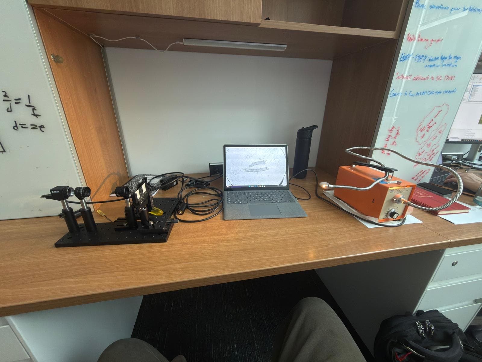
Planned experimental setup
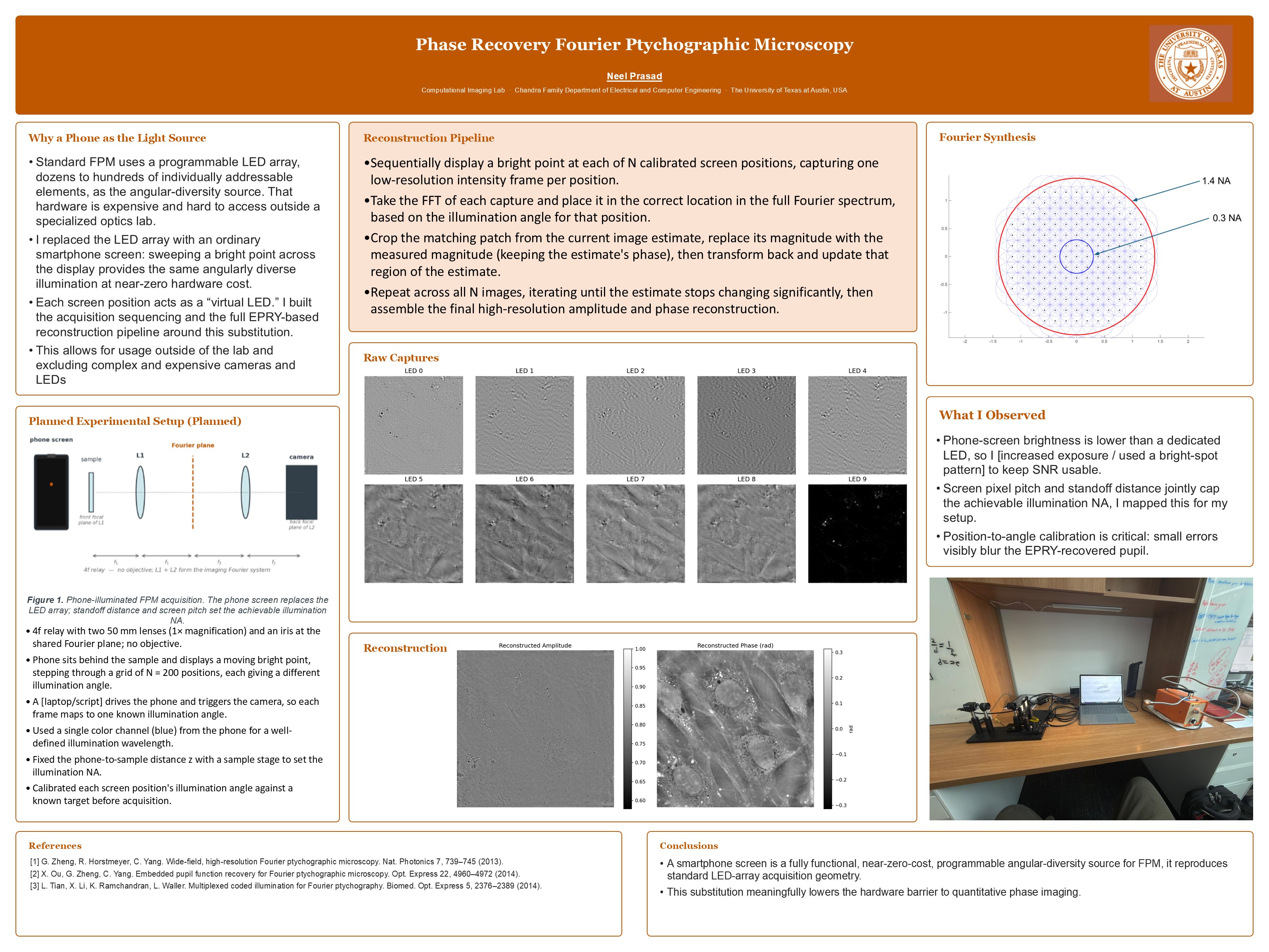
- A 4f relay with two 50 mm lenses (1× magnification) and an iris at the shared Fourier plane, with no objective.
- The phone sits behind the sample and displays a moving bright point, stepping through a grid of N = 200 positions, each giving a different illumination angle.
- A script drives the phone and triggers the camera, so each frame maps to one known illumination angle.
- A single color channel (blue) from the phone gives a well-defined illumination wavelength.
- The phone-to-sample distance is fixed with a sample stage to set the illumination NA.
- Each screen position's illumination angle is calibrated against a known target before acquisition.
Reconstruction pipeline
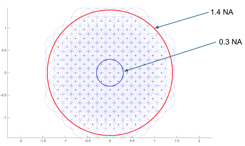
- Display a bright point at each of N calibrated screen positions, capturing one low-resolution intensity frame per position.
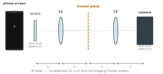
- Take the FFT of each capture and place it in the correct location in the full Fourier spectrum, based on the illumination angle for that position.
- Crop the matching patch from the current image estimate, replace its magnitude with the measured magnitude (keeping the estimate's phase), then transform back and update that region of the estimate.
- Repeat across all N images until the estimate stops changing significantly, then assemble the final high-resolution amplitude and phase reconstruction.
Results
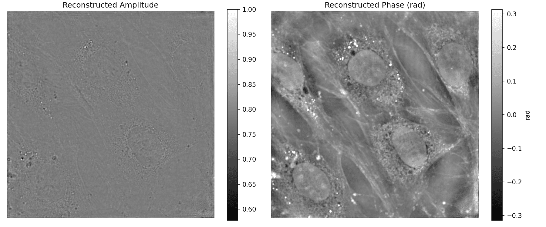
What I observed
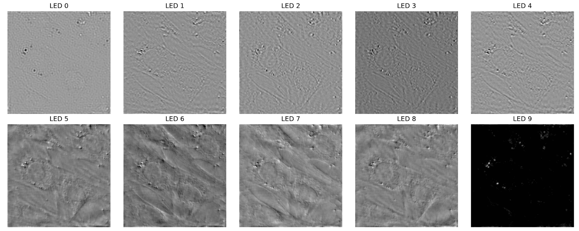
- Phone-screen brightness is lower than a dedicated LED, which makes keeping the signal-to-noise ratio usable a challenge.
- Screen pixel pitch and standoff distance jointly cap the achievable illumination NA. I mapped this for my setup.
- Position-to-angle calibration is critical. Small errors visibly blur the EPRY-recovered pupil.
Conclusions
- A smartphone screen is a fully functional, near-zero-cost, programmable angular-diversity source for FPM. It reproduces standard LED-array acquisition geometry.
- This substitution meaningfully lowers the hardware barrier to quantitative phase imaging.
References
- G. Zheng, R. Horstmeyer, C. Yang. Wide-field, high-resolution Fourier ptychographic microscopy. Nat. Photonics 7, 739–745 (2013).
- X. Ou, G. Zheng, C. Yang. Embedded pupil function recovery for Fourier ptychographic microscopy. Opt. Express 22, 4960–4972 (2014).
- L. Tian, X. Li, K. Ramchandran, L. Waller. Multiplexed coded illumination for Fourier ptychography. Biomed. Opt. Express 5, 2376–2389 (2014).